Home

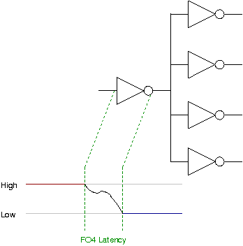
ندب النيكوتين عزل fo4 inverter كروي مطحنة فعالية

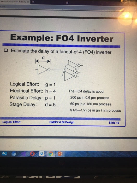
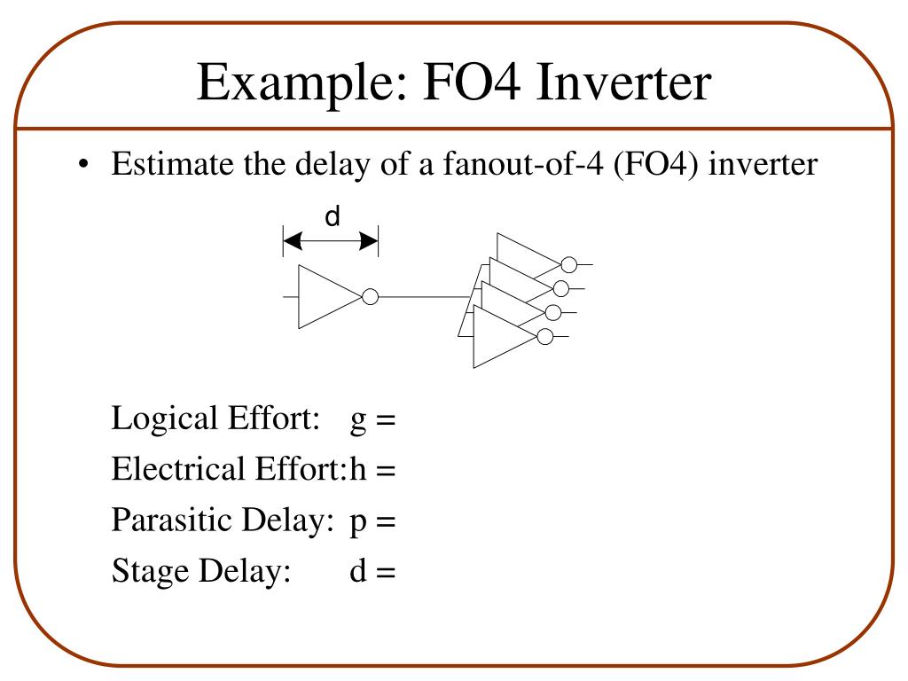
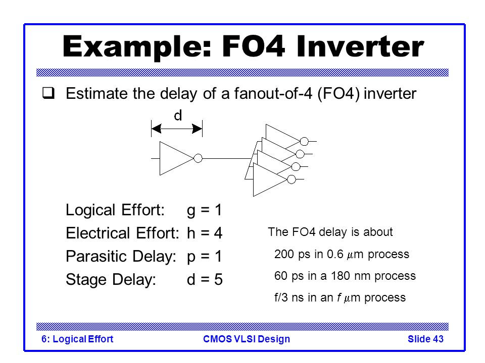
Introduction to CMOS VLSI Design Lecture 6: Logical Effort - ppt video  online download
Introduction to CMOS VLSI Design Lecture 6: Logical Effort - ppt video online download

Revisiting the FO4 Metric

ok so the example im about to put on here is a | Chegg.com

VDD Scaling (KN8421_FO2_LP2) (FO4 inverter delay is 51ps, 55ps, 61ps,... |  Download Scientific Diagram
VDD Scaling (KN8421_FO2_LP2) (FO4 inverter delay is 51ps, 55ps, 61ps,... | Download Scientific Diagram

디지털집적회로[2] - Fan-out, Inverter Sizing, Inverter Capacitance, FO4 : 네이버 블로그

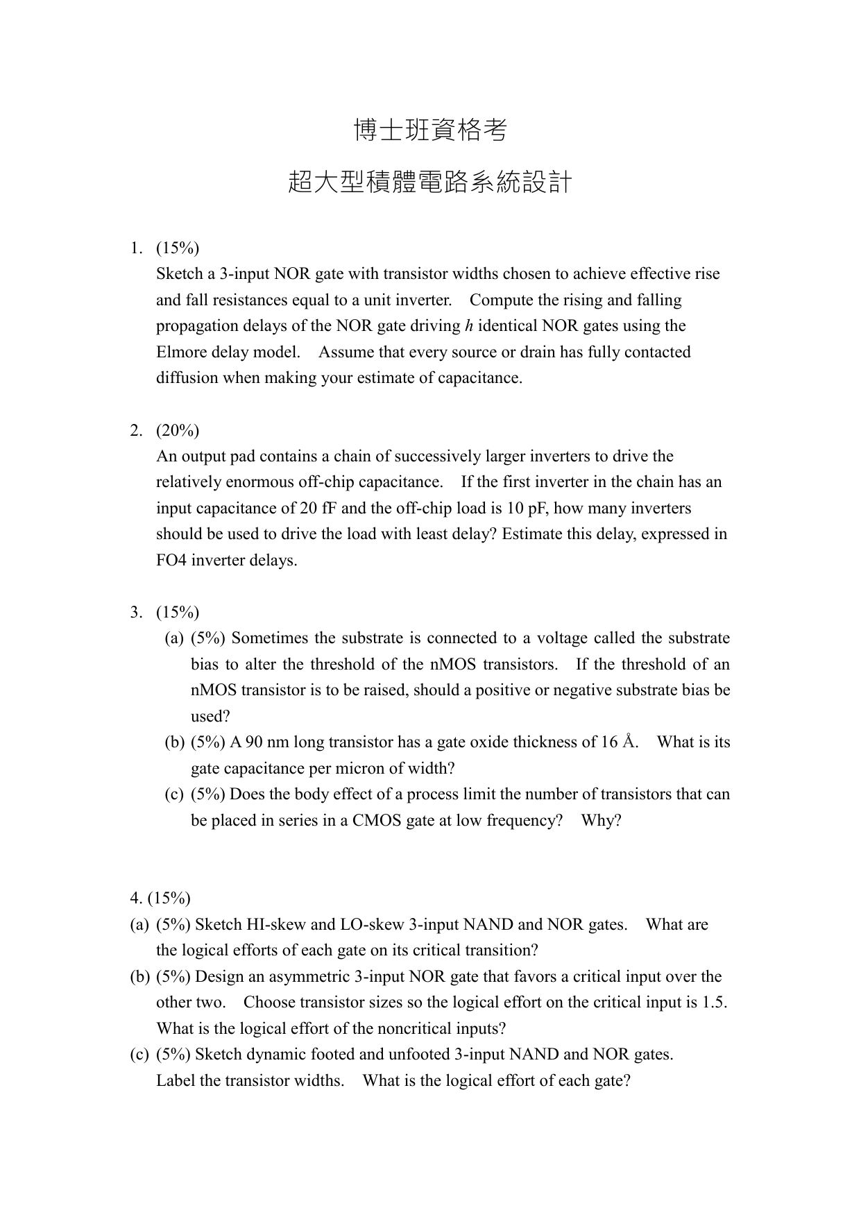
博士班資格考 超大型積體電路系統設計 (15%) Sketch a 3

a) Evaluating normalized leakage and delay of a 20-stage FO4 inverter... |  Download Scientific Diagram
a) Evaluating normalized leakage and delay of a 20-stage FO4 inverter... | Download Scientific Diagram

4) 10pt) Use the linear delay model to estimate the | Chegg.com

Gate Delay Model. Estimating Delays. Effort Delay. Gate Delay. Computing  Logical Effort. Logical Effort - PDF Free Download
Gate Delay Model. Estimating Delays. Effort Delay. Gate Delay. Computing Logical Effort. Logical Effort - PDF Free Download

Lecture 4 – Logical Effort - ppt video online download

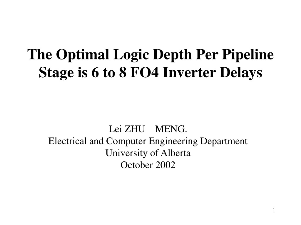
PDF] The optimal logic depth per pipeline stage is 6 to 8 FO4 inverter  delays | Semantic Scholar
PDF] The optimal logic depth per pipeline stage is 6 to 8 FO4 inverter delays | Semantic Scholar

CMOS Logic Gates a delay model Introducing logical

Evolution of I and total load capacitance of an FO4 inverter per width... |  Download Scientific Diagram
Evolution of I and total load capacitance of an FO4 inverter per width... | Download Scientific Diagram
PPT - Logic Gate Delay Modeling -1 PowerPoint Presentation, free download -  ID:1011335
PPT - Logic Gate Delay Modeling -1 PowerPoint Presentation, free download - ID:1011335

Solved Assignment #2 Q(1) Estimate tpd for a unit inverter | Chegg.com

Review : The Race for a New Game Machine

The Stuff Dreams Are Made Of [Part 2]

Part II CST SoC D/M Slide Pack 2 (Power): Gate Delay as a Function of  Supply Voltage
Part II CST SoC D/M Slide Pack 2 (Power): Gate Delay as a Function of Supply Voltage

Gate delay of FO4 inverter driving local interconnect. | Download  Scientific Diagram
Gate delay of FO4 inverter driving local interconnect. | Download Scientific Diagram

MICROELETTRONICA Logical Effort and delay Lection 4 1

PDF] The optimal logic depth per pipeline stage is 6 to 8 FO4 inverter  delays | Semantic Scholar
PDF] The optimal logic depth per pipeline stage is 6 to 8 FO4 inverter delays | Semantic Scholar

a) FO4 inverter and wire delay measurement setup and (b) simulated... |  Download Scientific Diagram
a) FO4 inverter and wire delay measurement setup and (b) simulated... | Download Scientific Diagram

The Stuff Dreams Are Made Of [Part 2]

Lecture 5: Logical Effort - PDF Free Download

PPT - The Optimal Logic Depth Per Pipeline Stage is 6 to 8 FO4 Inverter  Delays PowerPoint Presentation - ID:9436430
PPT - The Optimal Logic Depth Per Pipeline Stage is 6 to 8 FO4 Inverter Delays PowerPoint Presentation - ID:9436430