Home

واعد الدعائم الاتهام inverter logic gate النموذج المبدئي تناقض تعارض تضارب فرصة

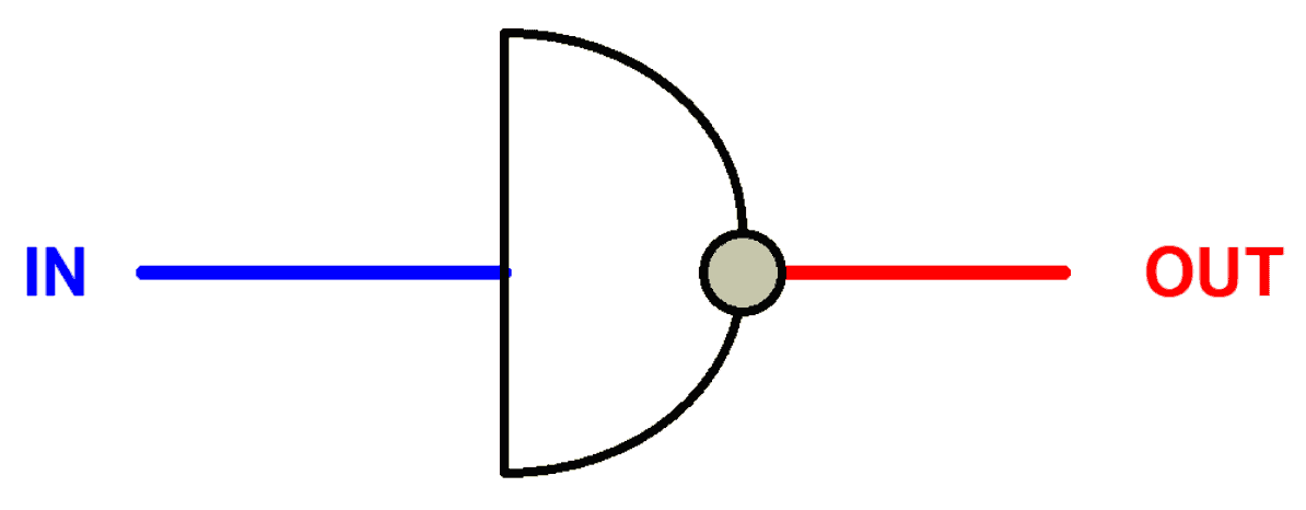
Logic NOT Gate Tutorial with Logic NOT Gate Truth Table

Logic NOT Gate - Digital Inverter Logic Gate - Electrical Technology

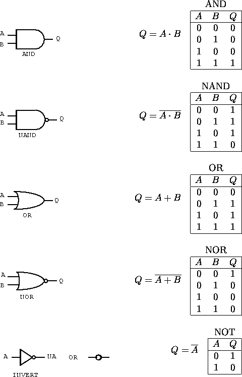
Logic Gates
Logic Gates

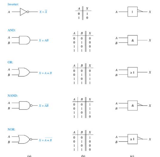
Gate Universality | Logic Gates | Electronics Textbook

M74VHC1GT14DTT1G onsemi | onsemi M74VHC1GT14DTT1G Inverter Logic Gate,  5-Pin SOT-23 | 805-1542 | RS Components
M74VHC1GT14DTT1G onsemi | onsemi M74VHC1GT14DTT1G Inverter Logic Gate, 5-Pin SOT-23 | 805-1542 | RS Components

Inverter (logic gate) - Wikipedia

a) Schematic of a p-logic Inverter and (b) a p-logic NAND gate. | Download  Scientific Diagram
a) Schematic of a p-logic Inverter and (b) a p-logic NAND gate. | Download Scientific Diagram

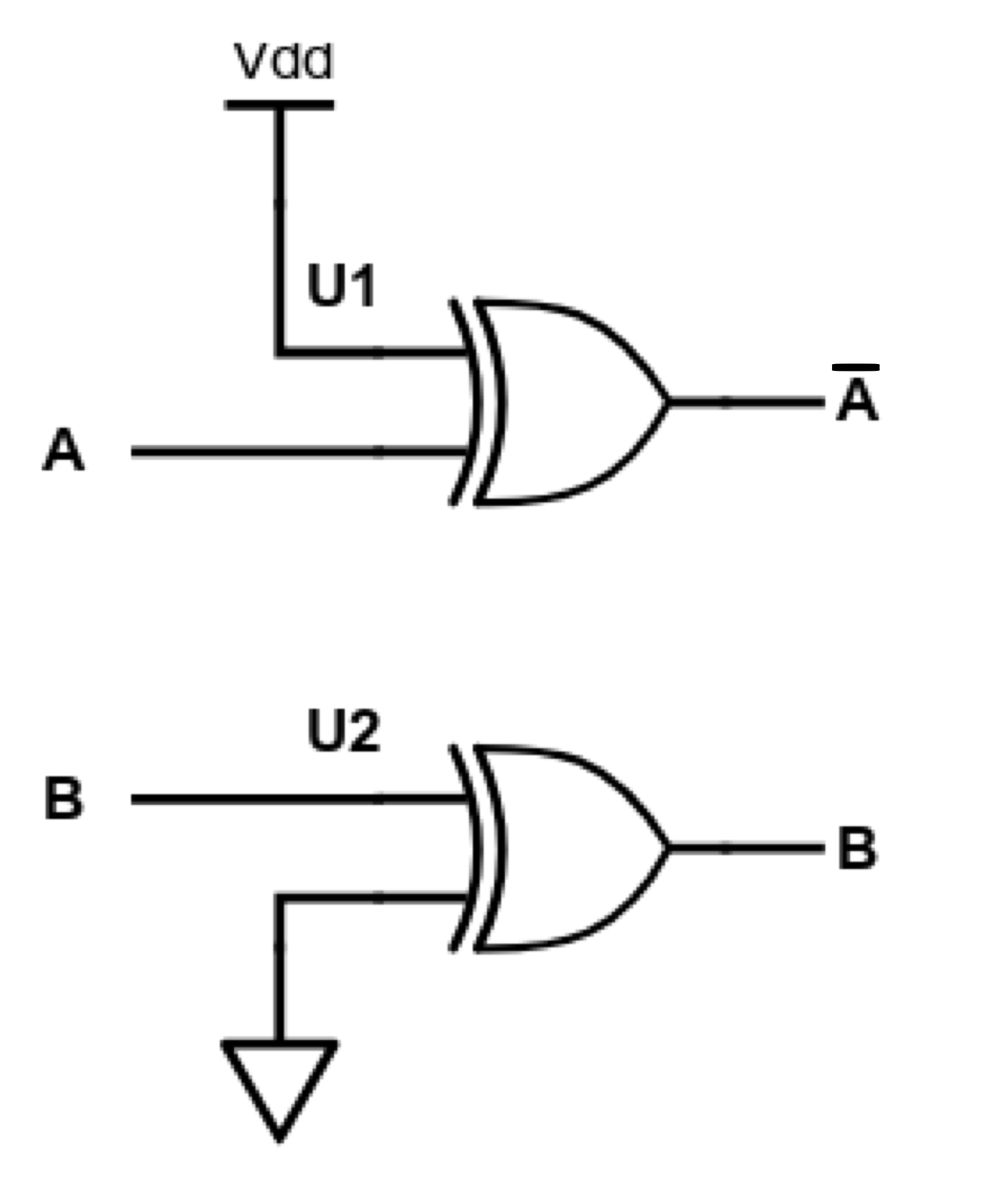
XOR Logic used as a Buffer or Inverter

Concepts II: An inverter | The negotiations were short

Transistor Logic NOT Gate - Inverter

Logic NOT Gate Tutorial with Logic NOT Gate Truth Table

Building 7 Transistor Logic Gates using And, Or, Exor and Inverter -  Electrical Engineering Stack Exchange
Building 7 Transistor Logic Gates using And, Or, Exor and Inverter - Electrical Engineering Stack Exchange

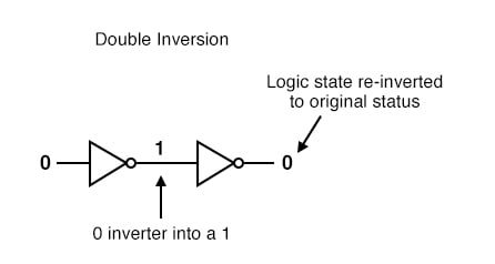
The “Buffer” Gate | Logic Gates | Electronics Textbook

Logic NOT Gate - How does a not gate work

NOT Gate: How Does it Work? (Circuit Diagram & Working Principle) |  Electrical4U
NOT Gate: How Does it Work? (Circuit Diagram & Working Principle) | Electrical4U

Logic NOT Gate Tutorial with Logic NOT Gate Truth Table

Logic NOT Gate Tutorial with Logic NOT Gate Truth Table

Basic Logic Gates
Basic Logic Gates

Inverter Logic gate OR gate Diode logic Electronic circuit, positive and  negative, angle, electronics, white png | PNGWing
Inverter Logic gate OR gate Diode logic Electronic circuit, positive and negative, angle, electronics, white png | PNGWing

Inverter Logic Gate NAND Gate NOR Gate, Gate PNG

Examples of logic gate implementation with SOTG cells. (a) Inverter.... |  Download Scientific Diagram
Examples of logic gate implementation with SOTG cells. (a) Inverter.... | Download Scientific Diagram
AOI (AND-OR-INVERTER) Cell |VLSI Concepts

Logic Gates - Digital Design | Analog Design | Turnkey | ASIC | SoC |  Embedded | Firmware
Logic Gates - Digital Design | Analog Design | Turnkey | ASIC | SoC | Embedded | Firmware

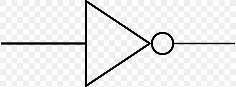
Power Inverters Logic Gate Electronics Wiring Diagram, PNG, 2400x886px,  Inverter, And Gate, Area, Black, Black And
Power Inverters Logic Gate Electronics Wiring Diagram, PNG, 2400x886px, Inverter, And Gate, Area, Black, Black And

How to Make Logic Inverter, Buffer Gates using BJTs

What is the working principle of CMOS inverter? - Quora